Worked example · EN 1993-1-1
Eurocode 3 steel beam check: a 7.5 m IPE 400 in S355, step by step
A complete EN 1993-1-1 member check on a realistic roof beam — bending, shear and lateral-torsional buckling — with every utilization computed by the FERS finite-element solver, not copied from tables. Lateral-torsional buckling governs, and by a factor of three over plain bending.
1. The beam
A single-span floor/roof beam, simply supported at both ends, carrying a uniformly distributed load. The compression flange has no lateral restraint between the supports — the situation where lateral-torsional buckling (LTB) matters most.
| Section | IPE 400 (hot-rolled I-section) |
| Steel grade | S355 (f_y = 355 N/mm²) |
| Span L | 7.5 m, simply supported |
| Load | w = 13 kN/m characteristic, uniformly distributed |
| ULS load factor γ | 1.35 → w_Ed = 17.55 kN/m |
| Partial factors | γ_M0 = γ_M1 = 1.0 |
| Lateral restraint | Compression flange unrestrained between supports |
| Self-weight | Not added (checked separately) |
2. Design effects
For a simply supported span under a UDL, the ULS design effects follow directly:
- w_Ed = γ · w = 1.35 × 13 = 17.55 kN/m
- M_Ed = w_Ed · L² / 8 = 17.55 × 7.5² / 8 = 123.4 kNm
- V_Ed = w_Ed · L / 2 = 17.55 × 7.5 / 2 = 65.8 kN
The FERS engine computes these internally from the finite-element model; the hand values above match its §6.2.5 utilization to two decimals — a useful cross-check.
2b. IPE 400 section properties
Geometry from the FERS section library (exported from the open-source FERS_core Python package — the same values the solver uses):
| Depth h | 400 mm |
| Flange width b | 180 mm |
| Area A | 84.5 cm² |
| I (strong axis) | 23 136 cm⁴ |
| I (weak axis) | 1 318 cm⁴ |
| W_pl (strong axis) | 1 307.6 cm³ |
| W_el (strong axis) | 1 156.8 cm³ |
| Torsion constant I_t | 50.9 cm⁴ |
| Warping constant I_w | 483 × 10³ cm⁶ |
Axis note: FERS reports strong-axis bending about its local z-axis, so the checker labels the strong-axis clause “Bending z”. In Eurocode catalogue notation this is the y–y axis (W_pl,y).
3. The EN 1993-1-1 checks
§6.2.5 — Cross-section bending
The plastic bending resistance is M_c,Rd = W_pl · f_y / γ_M0 = 1 307.6 × 10³ mm³ × 355 N/mm² = 464.2 kNm. With M_Ed = 123.4 kNm the utilization is 123.4 / 464.2 = 0.27 — the solver reports the same value. On cross-section strength alone this beam looks barely half used.
§6.2.6 — Shear
With V_Ed = 65.8 kN against the plastic shear resistance of the IPE 400 web, the solver reports a utilization of 0.10 — shear is nowhere near critical, as is typical for rolled sections on medium spans.
§6.3.2 — Lateral-torsional buckling
This is the check that actually sizes the beam. With the compression flange free over the full 7.5 m, the solver computes the elastic critical moment from the section's weak-axis inertia, torsion and warping constants, reduces it via the LTB buckling curve, and reports a utilization of 0.82. Working backwards, the buckling resistance is M_b,Rd = M_Ed / 0.82 ≈ 150 kNm — only about a third of the 464 kNm cross-section resistance.
Utilization summary (FERS solver output)
| EN 1993-1-1 check | UC |
|---|---|
| Bending z (6.2.5) | 0.27 |
| Shear y (6.2.6) | 0.10 |
| Combined N+M (6.2.1) | 0.27 |
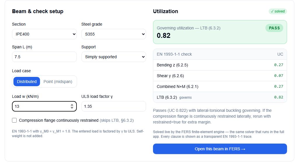
| LTB (6.3.2)governs | 0.82 |
Verdict: PASS, governing utilization 0.82 in lateral-torsional buckling. A beam checked on §6.2.5 alone would appear to have 3× more reserve than it really has — exactly the mistake the full clause trace prevents.
4. The same check, live in the browser
These are the exact inputs and solver results in the free FERS EC3 checker — no sign-up needed, solved by the same WASM finite-element engine that powers the full app:
Frequently asked questions
- Why does lateral-torsional buckling govern this beam?
- The compression flange is unrestrained over the full 7.5 m span, and an IPE 400 is slender about its weak axis. The solver's LTB reduction brings the bending resistance down from M_c,Rd = 464 kNm to M_b,Rd ≈ 150 kNm — roughly a 3× reduction — so §6.3.2 reaches 0.82 while plain cross-section bending is only at 0.27.
- What changes if the compression flange is restrained?
- With the flange continuously restrained (for example by a composite deck or closely spaced purlins with adequate stiffness), §6.3.2 is skipped and the cross-section checks remain: bending would govern at 0.27 for this beam. In the interactive checker, tick “Compression flange continuously restrained” to see this.
- Does this example include deflection (SLS)?
- No — this is a ULS resistance check to EN 1993-1-1. Serviceability deflections use unfactored (characteristic or frequent) combinations and separate limits; check them with the full FERS app or the free simply-supported-beam calculator.
Keep going
- Interactive EC3 steel beam checker — change the section, grade, span or restraint and re-run this example live.
- More examples — 3D viewer models, validation benchmarks and free calculators.
- Getting started — build the same beam from Python with fers_core.
Check whole frames, not just one beam
The full FERS Cloud app runs EC3 checks across every member of a 3D frame, with load combinations and many more section types.